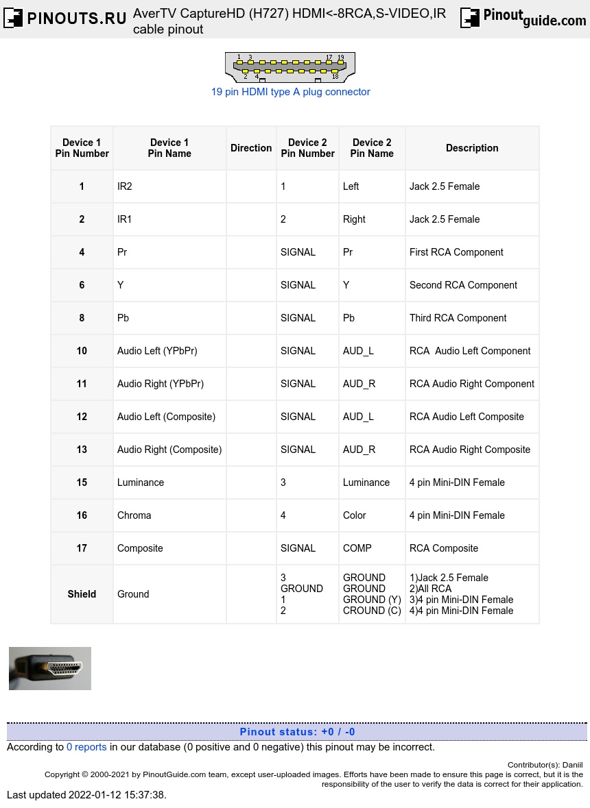
| Device 1 Pin Number |
Device 1 Pin Name |
Direction | Device 2 Pin Number |
Device 2 Pin Name |
Description |
|---|---|---|---|---|---|
| 1 | IR2 | 1 | Left | Jack 2.5 Female | |
| 2 | IR1 | 2 | Right | Jack 2.5 Female | |
| 4 | Pr | SIGNAL | Pr | First RCA Component | |
| 6 | Y | SIGNAL | Y | Second RCA Component | |
| 8 | Pb | SIGNAL | Pb | Third RCA Component | |
| 10 | Audio Left (YPbPr) | SIGNAL | AUD_L | RCA Audio Left Component | |
| 11 | Audio Right (YPbPr) | SIGNAL | AUD_R | RCA Audio Right Component | |
| 12 | Audio Left (Composite) | SIGNAL | AUD_L | RCA Audio Left Composite | |
| 13 | Audio Right (Composite) | SIGNAL | AUD_R | RCA Audio Right Composite | |
| 15 | Luminance | 3 | Luminance | 4 pin Mini-DIN Female | |
| 16 | Chroma | 4 | Color | 4 pin Mini-DIN Female | |
| 17 | Composite | SIGNAL | COMP | RCA Composite | |
| Shield | Ground | 3 GROUND 1 2 |
GROUND GROUND GROUND (Y) CROUND (C) |
1)Jack 2.5 Female 2)All RCA 3)4 pin Mini-DIN Female 4)4 pin Mini-DIN Female |
All ground pins connected to HDMI Shield. This device is identified as two separate capture card in OS: first for TV, composite/S-Video signals and IR, second for component/HDMI signals. That's why there two pairs of RCA Audio.


 correct
 incorrect